
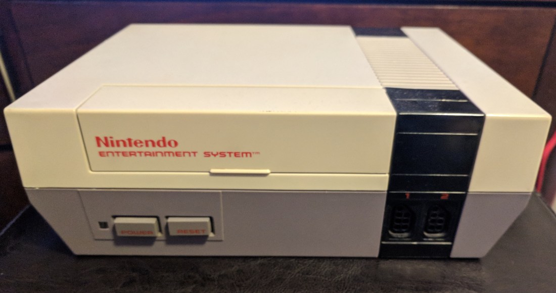
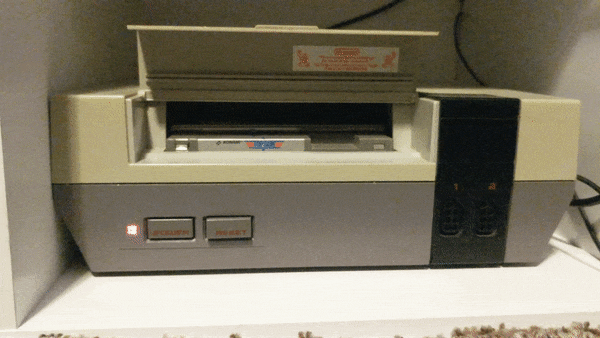
The Nintendo Entertainment System (NES for short) saw widespread release in the US in 1986, and quickly became the best selling video game console of its time. Although the 8-bit technology is now outdated, plenty of people still love to enjoy the classic titles released on this system such as Super Mario Bros. and The Legend of Zelda. However, after many years of use most of these machines fall victim to dust and debris getting clogged in the game cartridge reader causing no image to be displayed and a blinking red power light. In this simple tutorial, I will show you how to replace the 72-pin game cartridge reader so you can experience the nostalgia of playing some of your favorite childhood games.
Difficulty: Novice
Time: 10 – 15 Min
Total Cost: ~$10
You will need:

• Phillips Head Screwdriver (PH2)
• A new 72-pin connector(amazon link)
• Isopropyl Alcohol (As close to 100% as possible)
• A Cotton Swab
Start by disconnecting the NES from any source of power, then flip the device so the bottom is facing up.

Now we will begin the disassembly process. Start by removing the (6) screws from the bottom panel. After all of the screws have been removed, flip the console over and gently remove the top half of the shell.

The device should now be in two pieces, set the top of the shell aside.
Shift your focus to the bottom half of the enclosure and locate the (9) screws we need to remove to separate the metal RF shield from the cartridge reader and main board.


After removing all of the screws, lift the metal shielding off of the bottom assembly.


Now locate and remove the (6) screws securing the cartridge slot to the main board.
(NOTE: On reassembly, verify that the cartridge reader sticks down when depressed. If it doesn’t, loosen the two forward-most screws until it does)

Gently remove the cartridge holder from the main board by pulling away from the back of the device while lifting at a 30 degree angle. Do not force this step. If there is any resistance, just try different angles until it can be removed with ease.

Almost done! You should now just be left with the main board and the 72-pin cartridge reader. Now is a good time to blow out the system with compressed air to get rid of all that dust from the 80’s. Unless you are sentimental about that kind of thing.

Without unplugging any cables, gently lift the main board out of the lower shell until the 72-pin connector has enough room to be disconnected. If there is any resistance, double check to ensure you have removed all of the screws. Slowly push the old 72-pin connector off of the main board by placing your thumbs on the plastic tabs next to it.

Whew, the hard part is over! At this point we are ready to attach the new 72-pin connector. Some people have success after just cleaning the 72-pin connector with alcohol, unfortunately I was not one of those lucky people. If you wish to try this, follow the next step and then reassemble your machine to test it. If you aren’t feeling lucky today, skip the next step and continue on ahead.
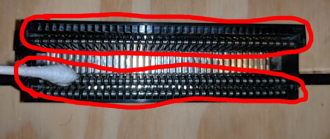
Using an alcohol soaked cotton swap, clean the two circled areas of your 72-pin connector (extra dirty connectors may need multiple cotton swabs) and let the alcohol COMPLETELY evaporate before reassembly. If it still smells like alcohol, it is not completely evaporated. You may also want to clean the board as shown in the next step too but after that you are done! Reassemble your machine and test it by loading in a cartridge. If you are still greeted by the same issue, you will have to follow the rest of the steps to completely replace the connector.

Using a rag or cotton swab soaked with alcohol, clean the contacts on the board shown in the image above. There are also contacts underneath the board so make sure to get those as well. Let the alcohol COMPLETELY evaporate before moving onto the next step. If it still smells like alcohol, it hasn’t evaporated yet.

Finally, install your new 72-pin connector onto the main board by sliding the double sided section onto the main board where the contacts are. Ensure that the plastic tabs are close to the main board so you know the connector is orientated correctly.
(NOTE: After installing my 72-pin connector, I still had to play with the positioning of the game in order to get it to display correctly. I found that inserting the game too far into the console will cause it to glitch out. The halfway mark was about the sweet spot for my console.)
You made it to the end! That wasn’t so hard was it? Now follow the steps in reverse order to re-assemble your machine so you can stomp on some turtles with everyone’s favorite Italian plumber! (Seriously someone needs to call PETA, that dude is a psycho.)

I hope you enjoyed this tutorial! Please leave feedback as to how I can better my content.
-B
